New workshop project.

Colin

Retired.
Joined
Sep 17, 2017
Messages
1,663
Reaction score
2,541
Location
Huddersfield.
Hardiness Zone
7
Country
United Kingdom
Hi,

Thanks Mary; we at least sing from the same hymn sheet. :)(y) There are so many people these days who need watering not feeding. One thing I have problems with is handing over small change at a supermarket checkout; the checkout assistant at our local "Home Bargains" store is always short of small change and I usually have a pocketful; what I do now is to pull out a handful of small change and place it in both my open hands saying please help yourself; it works a treat and I usually remark it's good to get rid of the scrap iron from my pocket . :)

I've enjoyed myself in the workshop today; this morning I started off sorting out switches to use; the industrial Modello 12A 550VAC rotary switch tormented me for quite a while until I decided to leave it alone; this switch has 12 connections 6 of these were strapped to form 3 pair. I was using my DMM (Digital multimeter) but couldn't get any sense out of the connections.

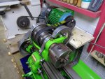
I then decided to sort out the Graduate lathe controls but obviously the on-off-on toggle switch and Potentiometer wouldn't simply fit into the existing holes these holes now being much too big and I'm not one to bodge a job so I looked around my stock of sheet metal and found a suitable lump of aluminium; I used the original mounting plate to draw around transferring the shape onto the aluminium which I then cut by hand in the vice using my hack saw. A few minutes spent on the 4" belt sander and I had a blank mounting plate of the correct size; mounting holes were marked at each corner and drilled. The plate looked rather scratched and bland so I gave it a facelift firstly using fine abrasive paper followed by lots of rubbing with Solvol Autosol now it looked much better. The switch and potentiometer bosses were measured then suitable sized holes were drilled in the plate to accept them; The black dial was added and the potentiometer was secured to the plate ensuring the marker on the knob aligned then the switch was also added; I've fitted this control plate to the Graduate just to check it fits regarding mounting holes and it does; I'll be soldering the control wires shortly. This amount of detail takes time but is always worth it in the finished result; I'm pleased by how it looks.

This afternoon I brought the wayward 3 phase rotary switch up to my desk with the DMM and I've just been playing around with it in comfort and having found out what connects to what I've drawn a rough connection diagram; I've wired these switches but a long time ago and I'm aware the connections can be baffling so it was a case of patience and taking notes; the DMM didn't always give a reading to complicate matters possibly through poor switch contacts?

I'm enjoying pottering around and it's been a lot warmer today but still wet as usual. The rotary switch connections remain untested but DMM continuity readings are as shown.

The original push button Start/Stop is now replaced by the toggle switch which gives start/stop but also forward and reverse; the potentiometer is now the speed control; I'm making good steady progress and double checking everything because electricity is involved and I don't guess.

Kind regards, Colin.


Lathe rotary switch connections..jpg
DSC00262.JPG
DSC00264.JPG
 

Colin

Retired.
Joined
Sep 17, 2017
Messages
1,663
Reaction score
2,541
Location
Huddersfield.
Hardiness Zone
7
Country
United Kingdom
Hi,

One of the best ways I have of solving problems is to awake at around 3am with the problem buzzing around inside my head. I've used resistors for years but connecting both these motor speed controls to one VFD is new to me in fact connecting both motors to a single VFD is new to me but it's fun. In simple terms a potentiometer is a variable resistor and the following might be a bit heavy going for a gardening forum but all information is useful and I learn a lot by experimenting.

The voltages used in the control circuits is low enough to be considered safe so I don't mind being open about what I'm doing. Connecting two 10K potentiometers either in parallel or series is easy enough but unfortunately I doubt it's going to prove an easy solution regarding controlling the speed of one motor at a time. I'm using two 10K potentiometers so the resistances are straightforward and only the connections need sorting out but how to connect?

The VFD powering a single motor requires the 10K potentiometer this giving full sweep between 0 and 10K Ohms. Now adding a second 10K potentiometer changes this because the values change; at the moment I'm unsure of how the different connections will work; if I turn one potentiometer to 0 on the first motor will the second potentiometer control the speed on the second motor and how will resistances be changed? As I say though this is fun for me and rather than give myself an headache I can very easily experiment with the items on the bench but possibly this is becoming too complicated so `I'm looking at types of switches to isolate the potentiometers saving lots of hassle; usually with a bit of thought there are a number of ways to resolve a problem? Heres some useful information;

http://www.brighthubengineering.com...explored-construction-and-working-principles/

https://www.electronics-tutorials.ws/resistor/res_4.html

https://www.electronics-tutorials.ws/resistor/res_5.html

https://forum.allaboutcircuits.com/threads/how-to-switch-between-two-potentiometers.54263/

Strange isn't it how something which at first glance appears simple but then quickly becomes complicated. I'm not an expert on electrics or electronics but I am nosy and like to learn; I could spend hours reading through the information on the web but many times I find it quicker to get into the workshop and experiment hands on; it's very easy to destroy electronic equipment with a single wrong connection but I'm aware of this; it's also easy to destroy electronic components just by handling them due to "static" but potentiometers are not sensitive to static.

Ideally I didn't want to add additional switches but I'm considering using a wafer type switch just to switch speed control potentiometers between the two motors and I think this will prove the easiest and most reliable solution?

Whilst restoring vintage radios I had lots of electronic components but the components I retained are now scattered around; I've just had a look in our front bedroom wardrobes but unfortunately couldn't find any wafer switches; I used to have many different types of these switches so I'll search the workshop. I'm not the sharpest tool in the kit but what I don't know I can learn and this is what all this is about; the new Poly-V drive belt arrived this morning so I can now play with both mechanical and electrical aspects of this project; I just love it. Here's a couple of pictures showing how hobbies can invade wardrobes.

Got to go dinners ready; after dinner I'm heading into the workshop; now this is what I call being retired and it's even dry and sunny which is very rare. :):):)

Kind regards, Colin.

DSC00265.JPG
DSC00266.JPG
 

Colin

Retired.
Joined
Sep 17, 2017
Messages
1,663
Reaction score
2,541
Location
Huddersfield.
Hardiness Zone
7
Country
United Kingdom
Hi,

I don't know how I cope with all this excitement; it hasn't rained today (so far) and the sun has been shining; I took Bron to Meadowhall Shopping Centre this morning to spoil her as much as I could then this afternoon I've enjoyed a couple of happy hours in the workshop.

The most important part of this project was sorting out how to arrange the new Poly-V drive; it's all come together successfully this afternoon; I stripped out the lathe headstock mandrel and back gear allowing the new Poly-V endless belt to be installed then reassembled the headstock and back gear; this is an easy job for me and I lightly loaded the end thrust bearing on the mandrel to eliminate any end float at the chuck. I took a great deal of time and trouble to be gentle and to keep everything very clean; I then went around with the oil can lubricating moving parts. Very little force is needed otherwise a lot of expensive damage can be done to the lathe.

Now for the real test; I placed the motor on it's mounting board and am very pleased indeed that the belt is the correct length and it will run without fouling anything. With the belt loosely installed I can now measure to make a new better fitting motor wooden mounting but won't install the motor proper until I've sorted out it's wiring; it's a lot easier to install the wiring with the motor on the bench where access is excellent than to secure the motor to the lathe then worry about the wiring?

The small reflective square to the motor pulley is the pick up for my digital rev counter; when I powered this motor up on the bench I ran it up to 3,000 rpm and thought that's a lot faster than the VFD states so I brought the VFD speed down to read 500 rpm and took a reading with the digital rev counter to find I was correct in that the motor was spinning at 885 rpm so if the VFD speed is linear then it's 3,000 rpm spins the motor at 5,310 rpm? I'm sure I can adjust the VFD parameters to bring the motor speed down; a motor speed of 3,000 rpm on the lathes is plenty fast enough although on test years ago I did run a motor up to 11,000 rpm on the bench using this VFD. What fun I have.

The pictures below show the original flat belt drive and the new Poly-V belt drive; the new pulley on the motor is the correct Poly-V pulley but I'm running the original stepped crowned pulley in the headstock I'm sure the new Poly-V belt will drive better than the old style flat leather belts. The motor and mounting etc could benefit from a decent paint job to match the lathe.

I can now relax and concentrate on the electrics; I've included a picture of the 550V rotary switch this has 12 terminals also a picture of a few assorted switches; I never throw switches away unless they are faulty and even then I strip out any small screws retaining these for future use; I also strip out anything useful on anything to be thrown away. :)

Kind regards, Colin.

DSC00267.JPG

I never throw switches away unless the switch is faulty.

DSC00268.JPG

Original flat leather belt drive to stepped crowned mandrel pulley.

DSC00269.JPG

New endless Poly-V drive belt being installed.

DSC00270.JPG

New motor mounting board to be made now final measurements can be taken.

DSC00271.JPG

Looking more like it.

DSC00274.JPG


550VAC rotary switch salvaged from scrapyard many years ago now to be of use.
 

Attachments

  • DSC00272.JPG
    DSC00272.JPG
    132.2 KB · Views: 212

Colin

Retired.
Joined
Sep 17, 2017
Messages
1,663
Reaction score
2,541
Location
Huddersfield.
Hardiness Zone
7
Country
United Kingdom
Hi.

High Danger regarding previous posts on burning wood patterns using high voltage.

My chum David jogged my memory of a story he posted to me regarding experimental use of very high voltages and it makes gruesome reading. I think considering this it to be prudent that I only post what I've done regarding the electrical work on my two lathes rather than how I did the work; many novices read these threads/posts and I don't want to encourage anyone to play around with lethal electricity. Sorry if I'm a spoilsport but better safe than sorry. (y)

http://www.henleystandard.co.uk/new...le-burning-wood-in-workshop-inquest-told.html

Kind regards, Colin.
 

Colin

Retired.
Joined
Sep 17, 2017
Messages
1,663
Reaction score
2,541
Location
Huddersfield.
Hardiness Zone
7
Country
United Kingdom
Hi,

I've made more progress in the workshop today. I've started to install the VFD making an enclosure for it to keep the dust off it also I've done some of the wiring but this is mains 240V so I won't go into detail but shortly I hope to add notes on the control wiring because this is safe low voltage and actually the most difficult part of the wiring to sort out. I did have to bring a short length of old heavy cable up into the bungalow to ask Bron to kindly identify the green so I could use the correct colour for Earthing; modern cable is easy because the earth wire is either bare or has striped insulation which I can easily identify. On this old cable I thought the lightest colour to be green but Bron says its grey; why do I have to be so hopelessly colour blind.

The pictures show work up to date but if I can get into the workshop for a few hours tomorrow without interruptions then I can move this job on a bit further; I'm not under any pressure but it will be nice to have both lathes fully sorted out. The weather forecasters are having a laugh saying arctic weather is on the way; I won't notice any difference; it was -3.5C when I was out early this morning.

Kind regards, Colin.

DSC00276.JPG


DSC00277.JPG


DSC00275.JPG
 

Colin

Retired.
Joined
Sep 17, 2017
Messages
1,663
Reaction score
2,541
Location
Huddersfield.
Hardiness Zone
7
Country
United Kingdom
Hi,

In spite of this dire weather I'm enjoying myself in the workshop; snow flurries today but it make a nice change from the rain.

I've done lots more wiring; both motors were connected first for power through the big rotary switch. Then I moved on to adding the control wiring from the VFD to the Graduate lathe; the Start/Stop and On/Off were easy enough through a simple On-Off-On switch; this switch when switched to either On positions controls Forward or Reverse; the switch is a "Latching" type the middle position is Off but once it is switched to either On the Graduate runs until the switch is switched to Off; Brilliant that's nicely sorted.

Now the more complicated pair of potentiometers; I decided to connect these through another toggle switch allowing each to be isolated meaning I could select the potentiometer for the lathe I would be using; I bought through eBay a 3 pole Double Throw Latching Toggle Switch ON-OFF-ON Panel mounting; to the front this switch has the toggle lever but to the rear it has 9 connectors as seen in pictures below.

The Graduate lathe is now fully operational; I completed its wiring yesterday. Today I've concentrated on the Lorch lathe. I've added strengthening braces to the motor mounting welding these in making the mounting a lot more rigid then after fettling I blew over with rattle can of black lacquer to tidy it up; next I made a new motor mounting board then also sprayed this black; both were then fully installed. Now to connect the new motor for the Lorch which I've just completed and the motor is now fully installed taking a lot of care to align the pulleys and adjust the drive belt for tension. I could now test the motor by switching the big rotary switch to "2" WOW it works; at the moment the Lorch is running on the Graduate remote controls but hopefully tomorrow I can add it's own remote controls; I'm not adding Forward and Reverse to the Lorch because Reverse isn't needed so a simple toggle switch will control the Lorch On/Off this being connected directly into the VFD but the Lorch potentiometer will be connected to the 3 pole toggle switch and this will be the moment of truth once I try it under power; I'm confident though that it will work. I'll draw the tested and working circuit diagram once the everything is working correctly. It looks so easy now it's all coming together. For the low voltage control circuits I've used "CAT 5" cable this cable has 8 wires arranged in four pairs and it's been perfect for this project having a pair of wires spare and it cost me nothing because I was kindly given a 300m boxed coil free of charge; as seen in the picture this cable solders very well indeed.

Apart from the dire climate it's been an enjoyable day today and lots of positive progress has been made; both lathes should soon be running then I can explain how the controls are arranged.

Kind regards, Colin.

DSC00278.JPG

Wiring under way with the power circuits. Remote control wiring still to add.

DSC00279.JPG

Cat 5 cable for low voltage remote controls.

DSC00280.JPG

Rear view of Graduate lathe remote controls; old test connection leads were removed; new leads soldered in.

DSC00281.JPG

Front view of Graduate remote controls showing ON-OFF-ON switch and Potentiometer speed control.

DSC00282.JPG

3 pole ON-OFF-ON toggle switch for both potentiometer control. Only one potentiometer can be used at a time. This is located next to the big rotary switch on the VFD enclosure.

DSC00285.JPG

New motor mounting completed ready for installation. Sprayed using a rattle can to tidy it up.

DSC00286.JPG

New motor mounting fully installed. Chuck removed for safety in case motor comes up to speed in reverse on test. An heavy chuck becoming detached can kill. The rotation of the motor can be changed easily.
 
Last edited:

Colin

Retired.
Joined
Sep 17, 2017
Messages
1,663
Reaction score
2,541
Location
Huddersfield.
Hardiness Zone
7
Country
United Kingdom
Hi,

I wandered into the workshop through the falling snow before 9 o'clock this morning keen to pick up where I left off on this project.

I connected the Lorch remote controls; the ON/OFF works perfectly but as expected I'm having problems connecting the potentiometer speed control. At first "power up" the lathe took off at high speed and the potentiometer quickly destroyed itself. I learn a lot from these mistakes and I'm not at all upset; I expected trouble so rather than bang my head against a wall I've pulled away for the time being because a bit of research will sort this problem out rather than keep burning potentiometers out.

In a previous post I explained what I was attempting to do and why but this first attempt with the Lorch potentiometer (Speed control) disproved my theory and having given it a bit of thought I'm pretty sure I know what happened. The 3 pole switch I installed to isolate each potentiometer from each other works but I now realize that the way the potentiometers are connected to this switch it allows "backfeed" through the VFD hence instead of 10K Ohms 20K Ohms connected; I need to do more research as to my options; I need to fully isolate the potentiometers from the VFD only allowing one at a time to be in control without influence from the other potentiometer; it's a problem and there is usually a solution so a bit of thought is called for; I often come across problems whilst attempting something new; of course I also connected the Graduate potentiometer the wrong way around so the dial was reading in reverse; a simple swapping of two connections in the VFD sorted this out.

I like to leave my comfort zone to try new things and I'm not scared of making silly mistakes or even looking stupid; it's much better than sitting around scared to do anything and if I share my mistakes others will have the information; I'll succeed because failure is never an option; I'm very near though and both lathes run through one VFD which I set about proving just the potentiometers to sort out then job done. The potentiometers only cost about £1 each; I don't like destroying components but I am experimenting after all and enjoying myself. :D

Kind regards, Colin.

An update; I think I might have solved the Potentiometer problem; I had given it a great deal of thought before buying and installing the 3 pole switch that I was sure would work so I've been backtracking to try to find what I've done wrong?

upload_2018-2-27_16-25-7.png


The Graduate lathe was working perfectly so I took details of the connections and drew them out on the computer with the resulting drawing seen above; what a simple mistake; please note V1 and 5V are transposed; I'm sure connecting the Lorch Potentiometer like this won't have helped? V1 should be the middle (wiper) connection; I'll inspect tomorrow.
 
Last edited:

Colin

Retired.
Joined
Sep 17, 2017
Messages
1,663
Reaction score
2,541
Location
Huddersfield.
Hardiness Zone
7
Country
United Kingdom
Hi,

This speed control potentiometer for the Lorch was tormenting me yesterday so after my last post I decided to wander down to the workshop at around 5 o'clock to investigate; I was hoping I had simply made a wrong connection but on connecting everything up I had double checked and checked again; I had used the same colour wiring for each connection such as red with red etc but as I'm hopelessly colour blind I snipped a short length of red wire and used this to compare colour; there are red and another colour I presume to be orange but apart they look like each other; only when I place them side by side to compare can I see one is a lighter shade than the other; this wasn't the problem either as the wiring was correct.

I thought the potentiometer had destroyed itself so I desoldered it and tested it using the DMM to be surprised; it was giving perfect readings? It was cold and I had enough for the day so quit.

Today started as usual with another interruption; it had put 2" of snow down during last night so straight after breakfast I was out snow clearing from all our paths in sub zero temperature but strangely this didn't bother me too much; it made a change from the twelve months of rain. After a mug of warming tea I then wandered down to the workshop to do more tests; by the time I reached the workshop and closed the door behind me I was a snowman down my front; it was a blizzard to the side of the bungalow so I needed to surface brushing most of the snow away; I felt perished and my hands were cold; living here in Huddersfield really is fun when the weather plays havoc with just about every aspect of my life. With the fan heater set on high I could at last make a start.

Something is definitely odd because I'm sure my idea should work regarding switching arrangements; the 3 pole switch does isolate both potentiometers if OFF is selected so it's got to be something else; perhaps its "cross talk" between the Cat 5 signal cable and the motor power cable both running next to each other; I tied the signal cable away from the power cable but no change; to be absolutely certain there couldn't be back feed between both potentiometers I snipped the Graduate potentiometer wires but still no change. I wondered if the Lorch potentiometer should be higher wattage after all it's only rated at 0.2W but with 5VDC on a signal voltage it should be fine after all the Graduate potentiometer works perfectly? I've ordered and paid for a number of 2W potentiometers but until these arrive I decided to experiment a bit; I then tried taking resistance readings at the VFD of the potentiometer cable; with the potentiometer set at 10K maximum I was getting a reading of only around 3K Ohms? I had bought a twin 10K potentiometer so I strapped the connections in parallel and a DMM reading now gave the expected 5K Ohms but at double the Wattage? With the twin potentiometers connected at last the motor fired up running slowly and without speed control so a bit of progress has been made. By now I was too cold to carry on with both feet asking if I wanted frostbite; I turned everything off but as I left the workshop it had been and was still snowing heavily so I did more snow shovelling before coming back into the warmth of the bungalow; my feet sure were cold as were both hands; what a way to sort out an electrical problem; if only I could work with workshop doors wide open with warm sunshine beaming in and no interruptions I would think I was on another planet; I can't get into the garden and now getting into the workshop is a real pain but I'm not giving up; tomorrow both the 3 pole switch is being removed as is the potentiometer Cat 5 cable; when in doubt go back to basics and start over; I'll try different cable of the same length but ensure this is well isolated from other cables and the 3 pole switch won't be used I'm determined to sort this out.

The instruction manual suggests both the 5V and 10V VFD supply can be used for remote controls but when I tried the 10V supply the potentiometer on the Graduate lost some of its rotation.

Sorry if this sounds like a moan but it's the environment I find I'm working under in retirement and I could only report good things but I find many of these problems whilst learning and trying something new; in spite of the weather I do enjoy these challenges because when I eventually succeed I can feel I've achieved something; if it was easy I'd quickly become bored. So near and yet so far.

Bron informed me this morning Maplin Electronics are closing; I'm not surprised because electronic components can be bought very cheaply online even with delivery costs added; from China they are unbelievably cheaper than buying here in the UK but with a long delivery time; this is so sad but only a fool would pay four times as much for something? Have a look at the price of potentiometers here in the UK and in China.

I took this picture of our rear garden but by the time I had put on my heavy clothes the snow was really coming down; I could get snowed on and moan or I could remain warm indoors and moan; I chose the snow.

Kind regards, Colin.

DSC00292.JPG
 
Last edited:

Colin

Retired.
Joined
Sep 17, 2017
Messages
1,663
Reaction score
2,541
Location
Huddersfield.
Hardiness Zone
7
Country
United Kingdom
Hi,

On with two pairs of socks; heavy work boots; two thick jumpers; heavy work coat; one wooly knitted hat with ear muffs; one flat cap over; coat hood pulled over these and a pair of rigger gloves; 220' of wide pathway; patio; 40' decking; around the new garden shed ; the driveway and finally find our Yeti under last night's snowfall all whilst the breeze was blasting me with powdery snow; I've never been keen on winter sports and all I want to do is spend some time in peace in my workshop. Retirement here in Yorkshire is a punishment rather than a pleasure.

Kind regards, Colin.
 

Colin

Retired.
Joined
Sep 17, 2017
Messages
1,663
Reaction score
2,541
Location
Huddersfield.
Hardiness Zone
7
Country
United Kingdom
Hi,

WOW: SUCCESS AT LAST.

After such a bad start today with the prolonged snow clearing I thought if I can work outside in such atrocious conditions then surely the workshop with the heater switched on will be a lot more welcoming?

I wrapped up again and wandered down to the workshop with fierce determination; no way was I going to quit on this project and it was time I took it back to basics to find the cause of the potentiometer problem.

What a very strange fault it turned out to be; the Graduate lathe was running perfectly with it's own potentiometer giving full speed control and the changeover switch for power between lathes also the Start/Stop controls were working perfectly; I had used about 8' of Cat 5 signal cable for the remote controls on the Graduate so used about 12' of this cable on the remote controls for the Lorch. The Graduate worked perfectly on speed control the Lorch didn't?

OK back to basics; I left the original Cat 5 cable hooked up to the Lorch but snipped out the potentiometer leaving only the Start/Stop connected to the VFD; I then cut another 12' of Cat 5 cable but this time I seperated three of the pairs selecting a single wire from each pair; there being 8 wires in total I simply twisted 5 of these together not being in use; one end of the cable I then soldered to the potentiometer; as I say it's back to basics so I was checking every stage and next job was to use the DMM to test for potentiometer function at the other end of the cable; great at around 10K Ohms this was now fine; on the original cable it measured only 3K Ohms?

Now I connected the potentiometer to the VFD taking great care to connect the three wires in their proper place but now I let the cable settle onto the workshop floor away from any other cable; I switched on the VFD and then switched on the Lorch to be greeted by low speed; wonderful as I turned the potentiometer control to bring the Lorch up to speed; at last I had the answer; I did state in an earlier post I was concerned about "cross talk" this is when two or more separate wires in close proximity interfere with each other; how strange and how difficult I found this to be the fault after all using the same kind of Cat 5 cable on the Graduate wasn't any problem at all; out of curiosity I took a voltage reading on the Start/Stop connections and it read 24VDC so separating the wires broke the crosstalk connection; I come across many of these weird problems whilst experimenting but this one was a real head scratcher to resolve. With dinner time fast approaching I decided to leave it alone for today having the satisfaction of knowing my idea worked; yes I can and am now running two different lathes through one VFD. I'll re-do the control cables and switches and tidy everything up shortly.

What a joy it is to have the Lorch now converted to Poly-V drive with variable speed; I'll connect the reversing facility whilst I'm tidying the cables; I might need it at some future time?

Having now got the lathes working it becomes clear to me that I could if I desired run more 3 phase machines from a single VFD with appropriate wiring and switches; if the motors are identical it makes it easier but if not it's only a case of adjusting VFD parameters to suit the motor to be used.

Anyone experimenting expects problems and as in this case I've gained a lot more knowledge; Cat 5 cable isn't suitable for this sort of work but because of the problem I've been researching and believe Cat 6 Shielded cable should work; my plan is to use two lengths of Cat 5 cable; one for Stop/Start the other for the potentiometer; I have lots of Cat 5 cable and I'm tight; just use the wires I need and ignore the rest.

The pictures below show my environment the garden picture taken just before I started snow clearing. The wiring in the VFD will be tidied up and heat shrink sleeving added keeping each set of wires together; the new control box I made from items I had to hand and it's located just above the Lorch. One job I would like to sort out is the big emergency kick switch on the Graduate; this is not a latching type so I'll have to look into how to convert it or see what switches I have in stock to replace it with; I'll report back on this.

I hope my ramblings make sense and I've added the story as it's unfolded; I'm now looking forward to using both lathes in anger. Once I start a project I stick with it until it's completed however difficult it becomes. The most difficult of problems is very easy once the answer is known; I got caught out with the cable on this but I won't be caught out a second time; in the VFD manual it states shielded cable should be used of at least 0.52mm (23AWG). The Graduate though and my previous Jubilee lathes ran OK without shielded cable; something just likes winding the big key up in my back. WHOOPEE.

Thanks for your patience. (y):)

Kind regards, Colin.


DSC00293.JPG

If it's not rain then its hail; sleet; blizzard or snow; where's this global warming?

DSC00294.JPG

This wiring will look much tidier shortly.

DSC00295.JPG


Remote control station for Lorch Lathe. Start/Stop toggle switch and speed potentiometer.
 

Colin

Retired.
Joined
Sep 17, 2017
Messages
1,663
Reaction score
2,541
Location
Huddersfield.
Hardiness Zone
7
Country
United Kingdom
Hi,

I hope I've now sorted out the connections and have drawn up a diagram; hope it's of use.

image001.png


Please note Supply Earth does not connect to R S T but to Earth on the VFD. Shielded cable is very important for the remote controls; the VFD responds badly to unshielded cable.

This VFD is rated at 2.2KW but happily runs 1.1KW with VFD parameter adjustment. I'm running from 240VAC supply on a 13A plug.

Only one motor can be run at a time; The toggle switches for Rev/For one must be set at "OFF" also the Potentiometer 3 pole toggle switch must be set for the lathe or machine selected. Both motors are identical but possibly other motor combinations can be used but the VFD parameters will have to be reset for each motor.

This is intended only as an experiment; VFD's are generally one VFD for one motor but I wondered if more than one machine could be run from a single VFD for anyone on a limited budget. Please note this works for me and I do NOT encourage any novice to play around with electric mains voltage it is lethal and a simple mistake could be the last mistake ever made.

The Graduate lathe ran happily on unshielded remote control cable but the VFD reacted badly for the Lorch on unshielded cable so I highly recommend shielded cable for the remote controls.

I have shielded cable on order so will convert the remote controls once it arrives. The Potentiometer toggle switch is 3 pole. All toggle switches and the rotary switch are "Latching" types; they are ON-OFF-ON.

Play safely.

Kind regards, Colin.
 

Colin

Retired.
Joined
Sep 17, 2017
Messages
1,663
Reaction score
2,541
Location
Huddersfield.
Hardiness Zone
7
Country
United Kingdom
Hi,

Many thanks Upsy Daisy. Yes we're keeping warm and comfortable. Hope you and hubby are doing likewise. (y)

Whoops; I checked and double checked and checked again but still made a silly mistake in the circuit diagram for the middle connection on the two Rev/For toggle switches should read "DCM" not "ACM". Sorry about this; I'm working from assorted notes on my desk it being rather too cold at the moment to check against the actual VFD.

Please refer to the instruction manual for manufacturers circuits and for setting up the VFD parameters; the instructions have lots of owners asking questions on the web hence I thought I'd post what works for me having got mine sorted.

Ref Page 37 in instruction manual

Kind regards, Colin.

upload_2018-3-3_14-47-48.png
 
Last edited:

Colin

Retired.
Joined
Sep 17, 2017
Messages
1,663
Reaction score
2,541
Location
Huddersfield.
Hardiness Zone
7
Country
United Kingdom
Hi,

I spent an happy hour in the workshop this afternoon adjusting the plain taper bearings on the Lorch lathe but found adjustment to be difficult; I could adjust and turn the mandrel by hand but under power the mandrel locked up? I've removed the mandrel etc for investigation as seen in the pictures below; I'm looking for high spots anywhere also the thrust bearing to see if there is a problem with it; at first glance everything appears OK but I'll take my time and then reassemble. No brute force in removing a lathe mandrel otherwise the lathe could end up being scrapped; gently does it using pullers and threaded rod with spacers. I might need to adjust leaving slightly more freedom but care is needed because too much freedom will knock out the lathe accuracy; I enjoy tinkering around like this. :):):)

Kind regards, Colin.

DSC00304.JPG
DSC00305.JPG
DSC00306.JPG
DSC00307.JPG
DSC00308.JPG
DSC00309.JPG
 

Colin

Retired.
Joined
Sep 17, 2017
Messages
1,663
Reaction score
2,541
Location
Huddersfield.
Hardiness Zone
7
Country
United Kingdom
Hi,

Success at last the Lorch is running and sounding very sweet indeed after a couple of hours work this morning.

The problem was found to be a very tight key preventing axial movement to allow accurate adjusting; the pictures show the high spot on the top of the key where it's polished. I nipped the mandrel in the big vice using scrap wooden packing to prevent causing damage; it's so easy to add dents or flats and once added these can and do cause no end of trouble; a few strokes with an engineers file reduced the height of the key but the shaft was still a tight fit so I patiently used fine abrasive paper to ease it until it was a nice sliding fit; all traces of abrasive dust was removed then it was just a case of reassembly.

Plenty of oil was added as assembly progressed; with the mandrel home NOT FORGETTING TO ENSURE THE DRIVE BELT WAS IN PLACE I adjusted the left hand "outboard" locking ring nut first spending quite a while until the mandrel could easily be turned by hand but having removed all "play" please note the two reference marks I added with a marker pen; these weren't needed in this case because the mandrel adjusted easily but I added them to show how something so simple can avoid lots of frustration; the marks indicate by how much the ring nut is adjusted. The back gear assembly was then installed and all guards fitted. The motor could now be attached and the moment of truth as the lathe was started under power.

I can't stress enough care is needed on a job like this and also cleanliness; a lathe or indeed any machine can be destroyed by rough dirty work; lubrication is a must as assembly proceeds; taper bearings don't like being run dry. I didn't do anything with the taper bearings other than look and feel for anything untoward like high spots; these bearings had bedded in so any rings marking would remain.

I'm still awaiting CAT 6 cable and when it arrives I can complete the job knowing both the Graduate and Lorch are now sorted regarding being powered from a single VFD; I love to try something different and I've found this project to be most interesting and rewarding; the Lorch is now a superb lathe with it's new Poly-V drive installed.

Thanks for your patience.

Kind regards, Colin.

DSC00311.JPG


Locking split ring nuts.

DSC00314.JPG

The Mandrel.

DSC00315.JPG

The mandrel nipped in the vice with wooden protection to avoid damage.

DSC00316.JPG

The shiny key top shows how tight it was and this was the problem preventing bearing adjustment.

DSC00317.JPG

Problem easily resolved by using an engineers file.

DSC00318.JPG

A couple of reference marks can prevent lots of frustration.

DSC00319.JPG


Reference marks to show the keyway position; keys need to be top to prevent them dropping out unseen.
 

Ask a Question

Want to reply to this thread or ask your own question?

You'll need to choose a username for the site, which only take a couple of moments. After that, you can post your question and our members will help you out.

Ask a Question

Members online

Forum statistics

Threads
26,741
Messages
257,960
Members
13,318
Latest member
chiefcommander

Latest Threads

Top